AGF Burner, Inc.

Since 1878

Home

About Us

Bakery Burners

Ball Joints and Ball

Brazing Tips/Blast Tips

Blowpipes and Torches

Catalog (PDF)

Custom Application Burner

Fabric Singeing Burners

Fishtail Burners

Fire checks

Flame Ignition and Safety

Flame Testing Apparatus

Furnace Burners

Gas Appliance Regulators

Glassfire Burners

Needle Valves

Neon equipment

Open Flame Burners

Oxy-Gas Ribbon Burners

Oxy-Gas Tips

Quartz Burner/Surface Mix

Ribbon Burners

Ring Burners

Venturi Mixers

Technical Information

Services

Links

Contact

Technical Information

  Manifold pressure at gauge #1, figure 1) above, measures the pressure delivered to the burner and this is specified in the AGF catalog for the burner in question. For gas air burners 8” W.C. at this point is common and 10”W.C. is usually the maximum. This gauge point should be at least 6” from the mixer. No valves should be used between the mixer and the burner. The use of valves in this area can cause air to be backed up into the gas line and could result in an explosion.

  In some cases where a mixture is split so that one mixer feeds more than one burner by means of a manifold you should go at least 6” from the mixer before splitting the flow and the split should be made with equal runs to each burner so that they will be balanced. A balancing plug or screw is sometimes used in one leg to permit some adjustment, but it must be made so that it cannot be used as a complete shut-off and cause back pressure into the gas line.


   When setting up your gas train, please use the pipe manifolding calculator as a rule of thumb to help reduce pressure loss when going from one pipe size to another(or multiple outlets). 

Air-Gas Burner Operational Instructions - Manual

1) Inspect to make sure of proper installation of the burner, Venturi mixer, needle valves, Air filter regulators, zero gas governors or gas regulators and other equipment. Insure that gas and air lines do not leak. After inspection you are ready to begin.
a. Needle valves on Venturi mixer should be closed
b. Set Air Filter Regulator to 20-30 PSIG
c. If solenoids are in line, the will need to be energized or manually opened.
2) Turn gas on using the needle valves (or another flow controller for gas) and spark ignitor until you have a gas rich lazy flame.
Turn gas needle valve open and light. Gas only.


1748ZN: 3" Flame. Fig. 11-55 Insert. Center Feed Connection. Style "X" manifold. 1/2" NPT pipe inlet, gas on only.
3) Start the addition of compressed air 

1748ZN, adding air to the gas mixture. You should obtain a blue flame when adding air.
4) Adjust Air and Gas unit Sharp Blue Flame Cones are obtained 

1748ZN with air and gas adjusted to obtain a sharp blue cone flame. The cone height on a figure 11-55 insert should be about 7/8” (.875”) inches from the face of the burner insert.

5) At This point you can lock the Needle valves in place (optional)
6) Set up Spark Ignition (see circuit schematic for proper installation of solenoids, spark ignitors, flame sensors, etc.)


Flame Treating Plastics

Surface Treatment of Polyolefins for Decorating and Adhesive Bonding

                Polyethylene and Polypropylene have chemically inert and non-polar surfaces.  Chemically inert and non-polar systems do not bond well with adhesion products.  Surface treatment is required for acceptable adhesion of decorations, coatings, and other adhesive products.  Oxidation of polyolefin surface may be performed by the use of a flame to produce a receptive polar surface.  A receptive polar surface will take adhesion products and increase the ease of plastic printing. 

The following comments are offered as a guide for surface treatment of specific fabrication methods:

1)      Plastic Sheet treating: for thin walled plastics, also called thermoforms plastics, flame treating is ideal.  Especially if the products is greater than 25 mils.  Warpage of the treated parts can be avoided by increasing the conveyor speed (if the treatment is being done by a machine with a conveyor), or increasing the distance from the burner to the treated part.  Both applications will reduce the BTU/hr energy transfer of the burner in respect to the plastic part. 

2)      Injected molded products: Flame treatment is ideal for injected molded products usually due to the size, shape, and thickness of the products.  Always try to avoid excess heat when treating injected molded products, because it may bring out flow marks in the product.  Excess heating can also remove the ‘gloss’ from the product. 

3)      Blow Molded Products: Flame treatment is ideal for the majority of blow molded plastics because of the shape and wall thickness.  The flame treatment will even maintain the glossy finish of plastics.

4)      Rotational Molded Products:  Flame treatment is ideal.

Long lasting surface treatment can be achieved easily with the proper equipment.  If the treated parts are stored appropriately, the parts will retain their surface treatment for a minimum of one year.  Be careful to reduce contamination of the parts prior to treatment. 

Common contaminants which reduce flame treating of plastics.

1)      Handling: Use clean white gloves to handle the parts.  Plastics which have been touched with ‘oily’ hands will not treat properly.

2)      Additives: Concentrations of slip, anti-bock, and antistats can adversely affect the level of treatment.

3)      Machine oil and grease: Grease and oil spots on parts will not treat.  Keep the parts clean and away from contaminants.

4)      Mold releases:  Mold should be kept away from the parts prior to treatment.

Surface treatment can be easily removed.  Treated parts should be handled with care.  Since the treatment of plastics is essentially invisible to the naked eye, circumstances that could contaminate treated parts should be avoided.  After parts are treated, avoid excess handling.  Under no circumstance, should the area of the part that was flame treated be handled.  Dust or dirt should be blown off with air or rinsed off with water, and allowed to air dry. 

Flame treated parts, Avoid:

1) Excess handling – The oil from hands can remove flame treatment.

2) Wiping parts – Wiping with paper towels or clothes can remove flame treatment. 


Flame Treating

                Flame treating polyolefins is a common method to alter the surface structure of the plastic to be made polar through the method of oxidation.  When flame treating, the main consideration should be the uniformity in which the part will have contact with the flame.  The distance of the treated part should not vary distance from the flame. 

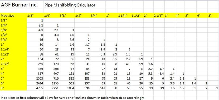
                The optimum distance to place plastics with an AGF Burner, Inc. Ribbon burner inserts is 3/8”-1/2” (inch) from the surface of the flame tips.  For example, a part to be treated with an AGF Burner, Inc. ribbon burner containing a figure 11-55 insert should be 1.25” to 1.375”(inch) from the insert face of the burner. 

                The surface of parts to be treated must be free from dust, grease, moisture, mold, or any other foreign containments.

Apparatus:

1)      Burner

2)      Air-gas Venturi mixer

3)      Air regulator

4)      Gas regulator

5)      Needle valves

6)      Gas supply (propane or natural gas)

7)      Compressed air or blower


Procedure:

1)      Calculate gas flow to give required BTU/hr output of the burners

2)      Calculate air to gas ratio

3)      Calculate air flow required to obtain 110% stoichiometric ratio.

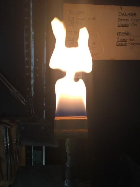
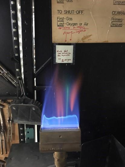
4)      Set air and gas flows, and ignite. 

5)      Set distance between visible blue tip of the flame and the part to be treated at ½” inch.

  1. If you are mounting the burner, attempt to set the burner at approximately a 30 degree angle from the perpendicular to push the heat away from the burner manifold.  If you mount the burner at 30 degrees, set the vertical distance at 0.433”(from the visible flame tips) for the first run. 
  2. Vertical and angular adjustability should be considered when building or mounting the burner.

6)      If you are using a conveyor, set speed at 75 feet per minute.

7)      Treat part and perform surface test.

8)      Slight adjustment should now be made to the air/gas ratio of the flame to obtain the optimum treatment of the parts.

  1. Adjustments can also be made to the distance of the burner to the treated part.    

Oxygen-Gas

The following precautions must be observed to obtain trouble – free operation of oxygen – gas burner equipment.

1)      Use the correctly sized AGF Burner, Inc.’s Venturi mixer for each burner set-up

2)      Install a fire check of suitable capacity between the Venturi mixer and the burners.  The fire check does not prevent a flashback, but retards combustion back into the mixture line in the event of a flashback.  These fire checks must be used in oxygen-gas burner installations.

3)      Do not install any valves, cocks, or restrictions other than a fire check between the Venturi mixer and the burners. 

4)      The Venturi Mixer should be placed as close as possible to the burners or burner manifold to avoid storing up too large a quantity of an explosive mixture. 

5)      All piping should be of sufficient size.  A common error that is made in burner installations is the use of under sized piping.  Whenever possible the mixture supply line to the burners should be of equal size or larger than the pipe size of the outlet of the Venturi mixer.

6)      Wherever possible, all fittings and piping directly connected to the oxygen-gas burners should be of copper or brass material to conduct heat away from the burners, thereby preventing over-heating.

7)      Make certain that there is no oil or grease in the fittings, piping, etc. of the oxygen-gas burner set-up.

8)      To minimize the possibility of flashing-back the following rule should be observed:

  1. Turn on gas, light;
  2. Turn on oxygen.
  3. Turning off – turn off oxygen first, then gas last.

9)      The gas and oxygen should be shut off immediately in the event of a flashback. 


Copyright 2011 AGF Burner, Inc.  All rights reserved. Flame treating plastic flame treating flame treating flame treating flame  flame treating plastic flame treating oxy-gas torch oxy-gas torch oxy-gas torch flame treat flame treat flame treat air gas air flame treating flame treating